Language: English











Cracks in New Buildings
Cracks in New Buildings: Causes and How to Fix?
CFRP fabric strengthening is an effective solution for restoring floor slab load-bearing capacity, but only after existing cracks are fully sealed by epoxy injection — otherwise, the CFRP system cannot arrest further propagation of active cracks.

Project Overview
| Item | Details |
|---|---|
| Location | Chengdu, China |
| Structural System | 16-story reinforced concrete shear wall structure |
| Floor Slab Type | Cast-in-place RC floor slab |
| Slab Thickness | 120 mm |
| Concrete Grade | C30 |
| Typical Span | 3.6 m (short direction) |
| Construction Stage | Main structure reached 8th floor |
The project is located adjacent to the Chenglu artificial lake area with significant diurnal temperature variation (average daily range 8–12°C). Multiple buildings were under simultaneous construction with overlapping workflow cycles, resulting in an aggressive construction schedule. After formwork removal on the 8th-floor slab, extensive diagonal cracking was observed on the slab soffit during inspection. The crack pattern showed significant regional variation: the mid-span region exhibited predominantly parallel diagonal cracks running in a consistent direction; the beam-grid panel boundaries displayed an intersecting grid pattern of transverse and longitudinal cracks; and the beam-column joint areas showed densely concentrated radiating cracks.


Crack
| Characteristic | Description |
|---|---|
| Pattern | Significant regional crack distribution variation: (1) mid-span region — multiple parallel diagonal cracks running in a consistent direction (aligned with the principal tensile stress direction of the slab span), non-intersecting; (2) beam-grid panel boundaries — intersecting grid pattern of transverse and longitudinal cracks at the junction of negative and positive moment zones; (3) beam-column joint areas — densely concentrated radiating cracks extending outward from the joint, present on both slab soffit and beam soffit |
| Maximum Crack Width | 0.45 mm (exceeds GB 50010 allowable limit of 0.3 mm for Class I environment by 50%) |
| Crack Depth | Full slab thickness (120 mm) — through-thickness cracks |
The three distinct crack morphologies correspond to different stress zones, collectively constituting a combined flexural-shear cracking mechanism.
Root Cause Analysis:
Premature formwork removal
To accelerate the 16-story building schedule, the project team removed all shoring systems merely 3 days after concrete placement — without obtaining the pass report from same-condition cured test cubes.
Internal Forces and Cracking Path
Mid-span section: Maximum bending moment → slab soffit in tension → insufficient concrete tensile capacity → parallel diagonal flexural cracks in a consistent direction (not intersecting);
Beam-grid panel boundary: Junction of negative and positive moment zones → combined transverse and longitudinal restraint → intersecting grid pattern of transverse and longitudinal cracks;
Beam-column joint: Maximum stress concentration → cracks radiate outward from the joint, present on both slab soffit and beam soffit, with larger widths and dark water staining;
At formwork removal, concrete strength was only 14.2 MPa, with estimated tensile strength ft ≈ 1.1–1.2 MPa (well below the 28-day standard value of 1.43 MPa). Under combined flexural-shear stress, the three distinct crack patterns initiated simultaneously across different zones.
Hazard
| Hazard Category | Specific Impact | Severity |
|---|---|---|
| Structural Capacity | Through-cracks reduce effective section depth, significantly decreasing flexural/shear load-bearing capacity | High |
| Reinforcement Corrosion | Seepage pathways allow moisture and O₂ to reach internal reinforcement; corrosion → rust expansion → concrete spalling → further crack widening | High |
| Serviceability | Seepage damages subsequent waterproofing membrane, floor finishes, and interior decoration, requiring extensive rework | Medium |
| Schedule & Cost | Crack repair and strengthening has a long cycle and high cost, paradoxically delaying the overall construction schedule | Medium |
Epoxy Resin Crack Injection
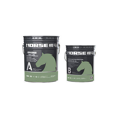
Injection Material Low-viscosity epoxy resin
process Cut V-groove along crack (10 mm wide, 15 mm deep)

clean groove

seal cracks


install injection ports (spacing 200–300 mm)


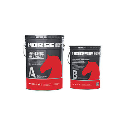
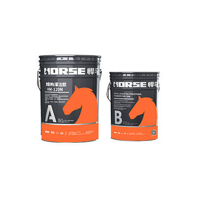
prepare crack injection adhesive

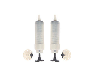
low-pressure injection (0.2–0.4 MPa)


CFRP Structural Strengthening
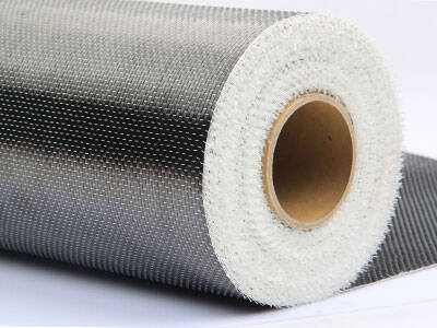
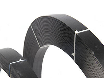
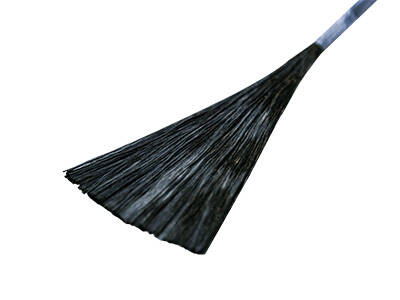
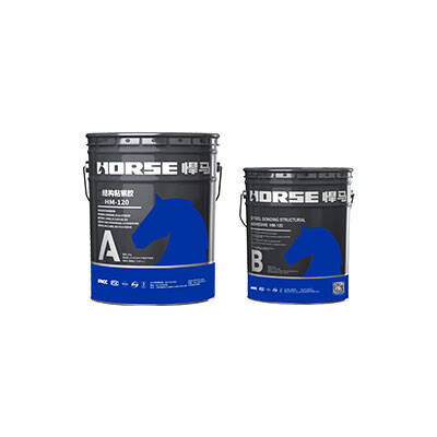
Uni-directional carbon fiber reinforcement polymer (CFRP) fabric was bonded to the slab soffit perpendicular to the crack direction, restoring flexural and shear capacity.