Reinforcement brick masonry structure
Carbon fiber fabric reinforcement brick masonry
The design scheme of this project is analyzed from four aspects of cost, construction period, service function and effectiveness of seismic performance improvement, and carbon fiber fabric reinforcement is determined as the optimal scheme.

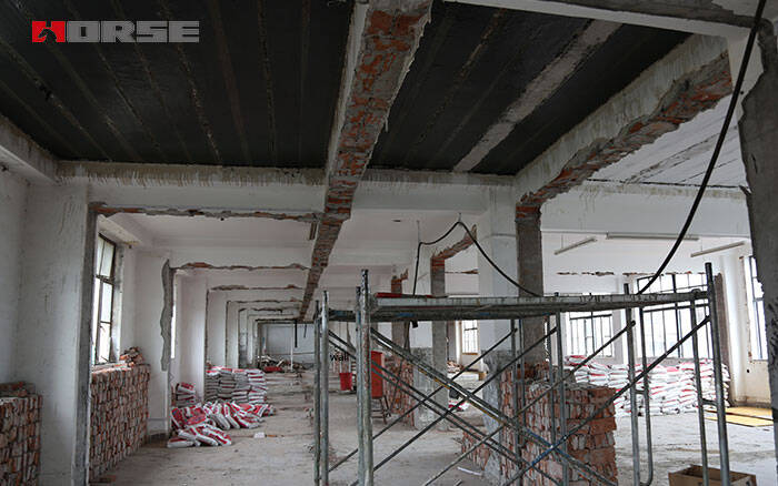
A teaching building in Shijingshan District of Beijing was built in 1986 with a floor area of 4300m. The first floor is a frame structure and the second to fourth floors are brick-concrete structures. The height of the first layer is 3.8 m, the height of the second and third layers is 3.6 m, the height of the fourth layer is 3.8 1 "13, and the total height is 14.8 M. It has been proved that the seismic capacity of the building can not reach the relevant provisions of the national primary and secondary school buildings safety engineering. After reinforcement, the seismic fortification intensity of the designed building is required to reach 8 degrees.
2.1 design plan
The design scheme of this project is analyzed from four aspects of cost, construction period, service function and effectiveness of seismic performance improvement, and carbon fiber fabric reinforcement is determined as the optimal scheme.
(1) If the traditional reinforcement method of reinforced concrete slab wall is adopted in this project, the beam-column section of the first floor frame will become very large with the increase of the upper load. It has a great impact on the use function of the first floor. Moreover, the foundation of frame column needs to be enlarged, even from independent foundation to raft foundation, resulting in the extension of construction period and the substantial increase of cost. Carbon fiber has the advantages of light weight, little additional load after reinforcement, little influence on building foundation, and little need for foundation reinforcement.
(2) The seismic appraisal report of this project shows that the compressive strength of the upper masonry structure meets the requirements, the shear capacity is insufficient, the number of original structural columns is insufficient, the cross-section of ring beams is small, the ductility measures of the wall need to be strengthened, and the carbon fiber fabric has the advantage of increasing the ductility of the structure.
(3) From the use point of view, the teaching building room clearance size can not be reduced too much, regardless of the length of the classroom or width direction to reduce more than 100 meters, the students will be extremely difficult to place desks and chairs, and the wall shotcrete reinforcement of the classroom clearance will generally reduce 160-200 meters. The use of CFRP fabric to reinforce the wall classroom generally reduces the headroom by only 50 to 60R a m.
2.2 main points of design
The key points of design include the selection of carbon fiber fabric, the determination of plane layout, anchorage mode and edge sealing measures.
(1) choose carbon fiber fabric. Brick masonry has low strength, poor ductility and poor adhesion between CFRP and wall, so it is not suitable to use high strength CFRP. Choose grade II CFRP of 200g.
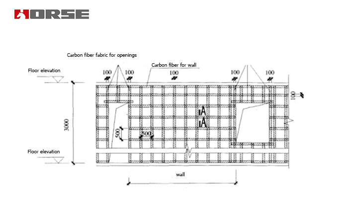
(2) layout of carbon fiber fabric. When the aspect ratio is greater than 0.5, the "well" type placement scheme is adopted, and the "eight" type placement scheme is adopted when the aspect ratio is less than 0.5.

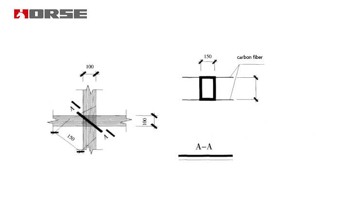
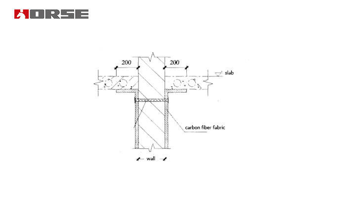
(3) anchorage measures. The anchoring measures have little effect on cracking load, but have great influence on the ultimate failure load. At present, a large number of experiments have proved that it is most reliable to adopt the anchorage method of pressing through the surface of carbon nails at the intersection of carbon fiber fabric. At the same time, the carbon cloth strips on the top of the wall are pasted 200 m long with the bottom of the floor, and the carbon fiber fabric are pressed on the surface of the carbon nails through the wall at 150 m below the floor.


(4) detailed design contents. The spacing of carbon fiber fabric, the layout of carbon nails, the joints and the sealing edges should be designed in detail. The design scheme of this project is that the main wall is strengthened by 200g CFRP single-layer two-way arrangement with 100m width. The longitudinal and transverse spacing is 500m. Carbon nails are used to press the intersection. The reinforcement schematic diagram of the joint of wall and floor is shown in the diagram.